Why Choose a DC DC Converter for Your Application?
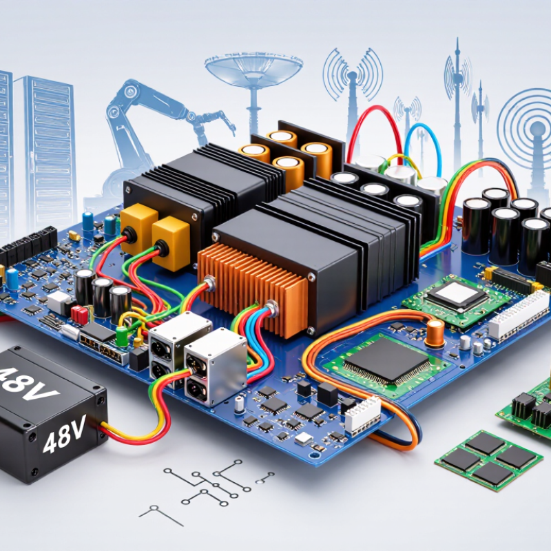
Power systems rarely receive the voltage they actually need. A battery may deliver 48 V, while a processor requires less than 1 V. A motor controller may need a stable 12 V rail. This mismatch is where a dc dc converter becomes practical. It adjusts voltage efficiently and can isolate sensitive circuits when required. It also helps engineers control heat, board space, and battery runtime. Small detail. Big consequence.
The need is increasing with electrification and digital infrastructure. The International Energy Agency’s Electricity 2024 report estimates that data centers consumed about 460 TWh globally in 2022. It projects demand could reach 620–1,050 TWh by 2026. These figures do not measure converter losses directly. They show why every power-conversion stage deserves careful review. The U.S. Department of Energy and Lawrence Berkeley National Laboratory reported that American data centers used approximately 176 TWh in 2023. Their report projects 325–580 TWh by 2028. In vehicles, telecom systems, robotics, and renewable equipment, efficient conversion can reduce wasted energy and stabilize changing inputs.
Choosing a converter should not begin with efficiency alone. Engineers must examine input range, output ripple, isolation, peak current, derating, thermal behavior, EMI, and protection features. A device rated at 95% efficiency may still become hot under continuous load. Real measurements matter. Prototype it. Test startup, faults, temperature rise, and full-load operation inside the final enclosure. Published curves may not match your wiring or duty cycle. That limitation is easy to overlook. A carefully selected dc dc converter, validated against field conditions, can support a cleaner, safer, and more dependable power architecture.
Map DC–DC Topologies to Voltage Needs: Buck, Boost, and Buck–Boost
A DC–DC converter earns its place when an application must change one DC voltage into another efficiently. The topology should follow the voltage relationship, not habit. A buck converter steps voltage down. It suits a 24 V rail feeding a 5 V controller or sensor. Its inductor stores energy while the switch cycles. Output ripple depends on frequency, inductance, and layout. Keep current paths short. A compact board can still produce measurable noise.
A boost converter raises voltage. It can convert a 12 V battery into a stable 24 V supply for actuators or LED strings. Input current may become substantial at lower battery voltage. Connector heating deserves attention. A buck–boost converter handles input levels above and below the target. This matters in battery systems, where a nominal 12 V pack may range from about 9 V to 16.8 V. Control becomes more demanding. Switching stress, ripple, and efficiency vary across the operating range.
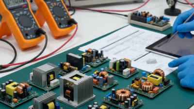
During selection, compare peak current, startup behavior, transient response, and thermal margin. Measure the real load, not only its label. I have seen a converter pass bench tests, then reset during a motor start. That gap is easy to miss. Use an oscilloscope at the load terminals. Check temperature after steady operation. Verify protection limits. Datasheet equations provide a sound beginning, but parasitic resistance and poor grounding can change the result. Leave room for revision. The first topology choice is not always the best one.
Measure 90–98% Efficiency to Reduce Heat and Battery Energy Loss
Why Choose a DC DC Converter for Your Application?
Measure 90–98% Efficiency to Reduce Heat and Battery Energy Loss
A DC DC converter earns attention when energy and temperature both matter. In practical testing, efficiency often reaches 90–98% under suitable operating conditions. That range matters in battery-powered equipment. Every lost watt becomes heat inside the enclosure. A 12-watt loss can quickly warm a compact device during continuous operation. Less heat can protect components and extend battery energy.
But efficiency figures need context. Measure input voltage, output voltage, input current, and output current under the same conditions. Repeat tests at startup, half load, and peak load. Use calibrated meters when possible. Record ambient temperature, airflow, and operating time. A converter may show 98% efficiency near its ideal load. At light load, performance can fall sharply. Real conditions are less tidy.
I once treated a single reading as typical. It was not. That mistake changed the test plan. For battery equipment, check quiescent current and thermal behavior too. If the enclosure feels warm after several hours, investigate the cause. Efficiency is not the only decision. Transient response, electrical noise, size, and protection features also affect reliability. A slightly lower peak efficiency may provide steadier performance in actual use. Careful measurement turns a datasheet figure into useful engineering evidence.
Size Inductors and Capacitors for Switching Above 100 kHz
Why Choose a DC DC Converter for Your Application?
Size Inductors and Capacitors for Switching Above 100 kHz
A DC DC converter can deliver stable voltage while using less board space. Higher switching frequency often reduces the required inductor and capacitor size. However, compact does not always mean better. At frequencies above 100 kHz, switching losses, magnetic heating, and electromagnetic noise become more noticeable. In practical designs, I check the load range, temperature, and expected efficiency before choosing the frequency.
Inductor selection starts with ripple current. A useful target is usually 20% to 40% of the maximum load current. For a buck converter, inductance depends on input voltage, output voltage, switching frequency, and ripple current. A smaller inductor may respond quickly, but it can increase ripple and saturation risk. Capacitor sizing also needs attention. Calculate the charge ripple, then check equivalent series resistance and voltage rating. Ceramic capacitors offer low resistance, yet their effective capacitance can fall under DC bias. I have seen designs pass bench tests and fail during hot operation. That mistake is easy to miss.
Tips: Keep short, wide current paths around the switch, diode, and input capacitor. Place the input capacitor close to the switching loop. Measure ripple with a properly grounded probe. Do not trust simulation alone. Recheck the worst case. Allow thermal margin, because a 100 kHz design can behave differently at 500 kHz.
Why Choose a DC DC Converter for Your Application?
Inductor and capacitor sizing for switching frequencies above 100 kHz
Calculated minimum values for a 12 V to 5 V, 2 A buck converter with 30% inductor-current ripple and 20 mV ideal capacitive ripple. Higher switching frequency reduces the required inductance and capacitance, while practical designs must also account for ESR, transient response, temperature, saturation current, and component tolerances.
Check Ripple, Isolation, and EMC Against IEC 62368-1 Requirements
Why Choose a DC DC Converter for Your Application?
A DC DC converter must deliver more than a stable output voltage. During bench testing, measure ripple at the converter pins and the final load. Use an oscilloscope with a short ground spring. Long probe wires can create false spikes. Check ripple during startup, shutdown, and sudden load changes. A quiet reading at half load proves very little. Thermal drift can also change performance. I have seen acceptable prototypes fail after several hours of operation.
Isolation requires careful review against IEC 62368-1. Confirm the working voltage, insulation system, creepage, clearance, and protective barriers. The converter’s isolation rating alone is not enough. PCB spacing, transformer construction, connectors, and the enclosure must work together. Small gaps matter. Isolation failures are rarely caused by one part only. This point is easy to underestimate.
EMC testing should include conducted and radiated emissions, immunity, and cable behavior. Add input filters only after identifying the noise path. Excessive filtering may create startup problems or reduce efficiency. IEC 62368-1 focuses on product safety, while detailed EMC limits usually involve related EMC standards. Treat both areas as connected, but do not treat them as identical.
Tips: Test with real cables and worst-case loads. Record ripple, temperature, and emissions together. Leave design margin. Then test again.
Why Choose a DC DC Converter for Your Application? - Check Ripple, Isolation, and EMC Against IEC 62368-1 Requirements
| Evaluation Dimension | Typical Engineering Target or Range | Why It Matters in the Application | Recommended Verification Method | IEC 62368-1 / EMC Relevance |
|---|---|---|---|---|
| Input Voltage Range | 9–36 VDC for a wide-input converter; verify the specified minimum, nominal, and maximum input values. | A wide input range supports battery systems, industrial buses, and automotive-style supply variation without additional regulation stages. | Test startup, shutdown, line regulation, and transient response at minimum, nominal, and maximum input voltage. | Input conditions affect insulation stress, abnormal operating conditions, heating, and protection design assessed during safety evaluation. |
| Output Voltage | Common regulated outputs include 3.3 V, 5 V, 12 V, and 24 V, with regulation typically within ±1% to ±3% under defined conditions. | The output must remain within the operating range of processors, communication interfaces, sensors, and downstream converters. | Measure output voltage at no load, nominal load, minimum input, maximum input, and after thermal stabilization. | Output voltage is not itself an IEC 62368-1 compliance limit; accessible energy and electrical protection depend on the complete equipment design. |
| Output Ripple and Noise | A practical design target is ≤20–100 mV peak-to-peak, measured with a defined bandwidth, probe connection, load, and input condition. | Lower ripple improves ADC accuracy, radio performance, clock stability, audio quality, and the reliability of sensitive digital circuits. | Use an oscilloscope with a 20 MHz bandwidth limit, short ground connection, controlled probing, and the specified load profile. | IEC 62368-1 does not generally prescribe a universal output-ripple limit. Ripple should be evaluated as a functional, signal-integrity, and EMC design parameter. |
| Efficiency | Approximately 85–95% is common for many modern DC-DC converter designs, depending on topology, voltage ratio, switching frequency, and load. | Higher efficiency reduces heat, enclosure size, fan requirements, and stress on surrounding components. | Calculate efficiency from measured input power and output power at 10%, 25%, 50%, 75%, and 100% load. | Temperature rise and fire enclosure considerations are important parts of equipment safety assessment under IEC 62368-1. |
| Galvanic Isolation | Typical isolated designs specify 1.5–3.0 kVrms dielectric withstand for 60 seconds; the actual value is construction- and application-dependent. | Isolation can separate hazardous or noisy circuits from user-accessible, communication, measurement, or low-voltage functional circuits. | Review the isolation barrier, transformer construction, insulation system, dielectric-strength test, and production test procedure. | IEC 62368-1 evaluates electric-energy sources, safeguards, insulation, and protection between circuits. Required isolation depends on voltage, energy, accessibility, and safeguard classification. |
| Creepage and Clearance | Values must be calculated from working voltage, overvoltage category, pollution degree, material group, altitude, and required insulation level; no single value applies to every design. | Adequate spacing limits arcing and surface tracking across the isolation barrier, especially in humid, contaminated, or high-altitude environments. | Perform PCB and mechanical inspection, verify the insulation system, and apply the applicable standard calculation tables and altitude corrections. | Creepage and clearance are central to insulation coordination and safeguard evaluation under IEC 62368-1. |
| Transient Response | A well-designed converter may limit output deviation to approximately 3–10% for a defined 25% to 75% load step, with recovery commonly within several hundred microseconds to a few milliseconds. | Fast recovery prevents processor resets, communication errors, sensor drift, and audible or visible disturbances. | Apply controlled load steps at different input voltages and record overshoot, undershoot, settling time, and control-loop stability. | Transient behavior is primarily a functional reliability concern, but abnormal conditions and protective responses may be relevant to the safety assessment. |
| Conducted and Radiated Emissions | Design toward the applicable equipment emission limits, often including conducted emissions from 150 kHz to 30 MHz and radiated emissions from 30 MHz to 1 GHz or higher. | Switching edges, common-mode currents, transformer capacitance, and long cables can interfere with radio, Ethernet, USB, audio, and measurement circuits. | Use a pre-compliance receiver, LISN, near-field probes, shielded test setup, and final testing in an accredited laboratory where required. | EMC emission requirements are normally addressed by applicable EMC standards, such as the relevant CISPR or IEC 61000 series, rather than by IEC 62368-1 alone. |
| Immunity to ESD and Fast Transients | Common evaluation levels include 4 kV contact and 8 kV air discharge for ESD, plus fast-transient testing according to the equipment environment and applicable standard. | A converter should maintain safe behavior and recover without permanent damage when connected equipment experiences electrostatic or switching disturbances. | Test operating, idle, startup, shutdown, and communication modes while monitoring resets, data corruption, latch-up, and recovery time. | Immunity is generally verified using IEC 61000-4 test methods and the applicable product EMC standard. Safety-related failure behavior must also be reviewed. |
| Surge and Input Transients | Test levels may range from hundreds of volts to several kilovolts depending on the port, installation environment, coupling mode, and product standard. | Protection against cable transients reduces failure risk in industrial, telecom, outdoor, and long-wire applications. | Select surge and transient waveforms according to the product environment; verify clamping, fuse behavior, restart, and absence of hazardous damage. | Applicable EMC immunity standards define the test method. IEC 62368-1 remains relevant to fire, electric shock, and energy-source hazards after foreseeable faults. |
| Protection Functions | Recommended functions include input undervoltage lockout, output overvoltage protection, current limiting, short-circuit protection, and thermal shutdown. | Protection limits component stress and helps the system recover safely from overloads, blocked outputs, incorrect connections, and abnormal temperatures. | Test each protection threshold, response time, repeated fault cycling, restart mode, and worst-case component temperature. | Protection and safeguard behavior support the IEC 62368-1 assessment of abnormal operation, fire enclosure requirements, and hazardous-energy limitation. |
| Operating Temperature | Common industrial ranges are approximately −40°C to +85°C ambient, with output derating above the converter’s rated temperature. | Temperature affects efficiency, capacitor life, semiconductor stress, startup behavior, and long-term reliability. | Measure case and component temperatures at maximum input, maximum load, minimum airflow, and the highest specified ambient temperature. | Temperature rise, material flammability, and abnormal operating conditions are relevant to IEC 62368-1 safety evaluation. |
| Compliance Documentation | Maintain schematics, PCB layout data, transformer and insulation construction details, risk analysis, test reports, and component safety documentation. | Complete records shorten certification review and make design changes, supplier substitutions, and production audits easier to control. | Review the technical file against the final bill of materials, production controls, safety-critical components, and applicable test plans. | IEC 62368-1 compliance applies to the finished equipment and its safeguards; a standalone converter specification cannot by itself guarantee system-level compliance. |

Note: The values shown are general engineering targets and typical test ranges, not universal regulatory limits. Final requirements depend on the converter topology, system voltage, installation environment, applicable national regulations, and the complete equipment design.
Compare Power Density in 400 V and 800 V Automotive Systems
Why Choose a DC DC Converter for Your Application?
Compare Power Density in 400 V and 800 V Automotive Systems
A DC DC converter links the high-voltage battery with 12 V or 48 V vehicle loads. It supplies controllers, lighting, pumps, and safety systems. In a 400 V system, a 10 kW load draws about 25 A. At 800 V, the same load needs only 12.5 A. Lower current can reduce copper size, resistive losses, and connector heating.
This difference can improve power density across the battery system. Smaller busbars may release valuable packaging space. Cooling hardware may also become less demanding. However, 800 V operation brings stricter insulation, creepage, clearance, and electromagnetic compatibility requirements. The converter needs components with suitable voltage margins. These parts can increase cost and design complexity.
A practical DC DC converter must handle a wide input range, fast load changes, and harsh thermal conditions. Bench testing often exposes issues that calculations miss. A cable may remain cool while a connector pin overheats. That detail matters. Engineers should compare efficiency at real driving loads, not only at rated power. The voltage-only argument is incomplete. An 800 V converter may offer excellent density, yet poor switching behavior can erase the benefit. Designers also need controlled startup, isolation where required, fault monitoring, and stable 12 V output during battery transients. Some early designs overvalue peak efficiency. Continuous partial-load performance deserves equal attention.
Related Posts
-
2026 Top Types of DC DC Converters for Global Buyers
-
How to Choose the Right DC DC Power Supply for Your Needs?
-
How to Choose the Right Buck Converter?
-
2026 Best AC to DC Inverter Types for Global Buyers
-
What is an Ups Electrical System and How Does it Work?
-
Understanding High Voltage DC Power Supply Benefits Applications and Safety Tips
At Premium PSU, we are specialists in designing and manufacturing power conversion systems for the industrial market. Our product range includes high reliability power supplies from 50W to 72kW.
PREMIUM PSU
C/ Dolors Aleu, 19-21, 2nd Floor
08908 – Hospitalet de Llobregat
Barcelona-SPAIN
t.+34 93 223 26 85