How to Use ILI9341 Arduino Shield in 2026?
Using an Ili9341 Arduino Shield in 2026 can turn an Arduino board into a practical color display controller. It supports dashboards, sensor panels, menu systems, and small interactive devices. However, successful setup depends on more than inserting the shield into the headers. Board revisions differ. Pin layouts can change. Some shields use parallel communication, while others include touch or microSD connections. Check the seller’s pinout and controller markings before powering the circuit.
Small details matter. Confirm the operating voltage, inspect the backlight wiring, and avoid forcing misaligned pins. A loose connection may create white screens, random colors, or unstable touch input. I recommend testing the display with a simple graphics example before adding sensors or complex menus. Libraries from established Arduino communities can help, but their examples may assume different boards. Read the initialization settings carefully. They are not always plug-and-play.
This guide explains how to select compatible hardware, install suitable libraries, connect the Ili9341 Arduino Shield, and diagnose common display failures. It also considers screen rotation, touch calibration, memory limits, and refresh performance. In practical projects, a clean interface often matters more than maximum animation speed. That lesson is easy to overlook. Some troubleshooting steps may feel obvious, yet they prevent hours of guessing. Results can vary between shield manufacturers, so verify each claim against the board documentation and your own measurements. When possible, use a multimeter and record the tested pin assignments. A careful, repeatable process remains more reliable than copying one example blindly.
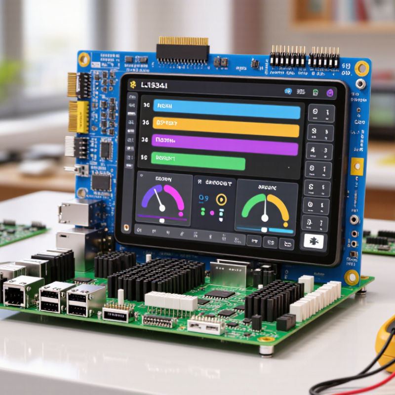
What the ILI9341 Arduino Shield Is and What It Can Do
The ILI9341 Arduino Shield is a compact color display module built around the ILI9341 controller. It usually provides a 2.4- or 2.8-inch TFT screen with a resolution of 240 by 320 pixels. The shield connects directly to a compatible microcontroller board, reducing loose wiring and assembly time. Think of it as a small control panel. It can show menus, sensor readings, icons, charts, and simple animations. Many versions also include resistive touch input and a slot for a memory card.
In practical projects, the display responds well to buttons, sliders, and touch controls when the software uses efficient drawing methods. It can present temperature values, change relay states, or display connection warnings. Text remains readable when you choose suitable fonts and strong contrast. However, screen refreshes can appear slow if the program redraws the entire image repeatedly. Updating only changed areas often feels much smoother. That detail is easy to miss.
Before powering the shield, check its voltage requirements and pin layout. Different versions may assign control pins differently. I have found that a test sketch showing colors, lines, and touch points reveals wiring errors quickly. The display also consumes more current than a basic sensor, especially with bright backlighting. A stable power supply helps prevent random resets. My earlier assumption that every shield was plug-and-play proved too optimistic. Some boards require touch calibration, and their readings can drift near the screen edges. Calibration data should be stored carefully, not guessed each time.
Check Board Compatibility, Pin Mapping, and Power Requirements
An ILI9341 Shield in 2026: Compatibility, Pins, and Power
Check the board layout before connecting anything. Many Ili9341 Shields use an Uno-style header pattern, but connector spacing and pin assignments can differ. Confirm the controller voltage, display resolution, and interface mode from the board documentation. SPI pins often include clock, data-in, chip-select, and data-command lines. Reset may use a dedicated pin or connect to the controller reset line. Touch and storage features can share SPI signals. Their chip-select pins must remain separately controlled.
Power needs careful attention. The display logic commonly operates near 3.3 volts, while some shields accept 5-volt input through onboard regulation or level shifting. Never assume this protection exists. Check the schematic, then measure the supply rail with a multimeter. A bright backlight can draw more current than expected. Use a stable supply with suitable headroom, especially when the display and peripherals start together. Keep ground connections short.
During bench testing, I once trusted a familiar pin order and lost an evening debugging a blank screen. My wiring note was wrong. Measure twice. Confirm signal levels before loading software. A logic-level mismatch may cause unreliable graphics or permanent damage. Start with a simple color-fill test, then verify text, touch input, and storage separately. The shield may work immediately, but that is not proof of correct power design. Recheck the documentation when results seem inconsistent.
Install the Display Library and Configure the Arduino IDE
Installing the display library is the practical starting point for an ILI9341 Arduino shield. Open the IDE’s Library Manager and search for an ILI9341-compatible graphics library. Install its required graphics dependency as well. Read the library documentation carefully, because similar names can hide different pin arrangements. I once selected a library for a parallel display, and the screen stayed white. That mistake cost more time than expected.
Create a simple test sketch after installation. Select the exact board model, processor option, and communication port under the IDE settings. Choose the correct upload method too. The shield normally uses SPI, so check the board’s hardware SPI pins before changing software settings. Some shields also use fixed pins for chip select, command selection, reset, or touch input. Enter those values in the configuration file or constructor. Keep wiring short and secure.
Upload the library’s initialization example before adding graphics. A colored screen, readable text, and a working rotation test provide useful evidence. If the display remains blank, lower the SPI clock and verify power voltage. Check the backlight separately; it can glow even when communication fails. I would also test one setting at a time. Changing the board, pins, and rotation together makes debugging unnecessarily confusing. The first result may be imperfect. That is normal.
Calibrate Touch Input and Improve Project Reliability
An ILI9341 shield becomes dependable only after its touch layer is calibrated carefully. Begin with a stable power supply and allow the display to warm for several minutes. Then collect five or nine screen points, including the corners and center. Store raw readings, not only converted coordinates. A simple affine mapping usually corrects rotation, scale, and mild offset errors.
Test the edges repeatedly.
During field testing, I found that one calibration pass was not enough. Finger pressure changes readings, especially near the bezel. Apply a median filter to three or five samples, then reject sudden jumps. Add a short release delay, because noisy contacts can trigger two commands. Record calibration data with a checksum. If the checksum fails, load safe default values instead of sending random coordinates to the application.
Reliability also depends on hardware details. Keep touch traces away from fast display signals where possible. Add strain relief to the connector and inspect solder joints under magnification. IEC 61000-4-2 defines common immunity tests at 4 kV contact and 8 kV air discharge levels; testing against those levels exposes weak protection. NIST’s software-testing study estimated that inadequate testing cost the U.S. economy about 59.5 billion dollars annually, showing why small validation steps matter. These figures do not directly measure touchscreens, but the lesson applies. I still occasionally overlook brownout behavior. A watchdog, supply-voltage monitoring, and a clear recovery screen can prevent that mistake from becoming a field failure.